Compare machine models
Check hot-press, cold-press and small-shop models by batch capacity.
Open page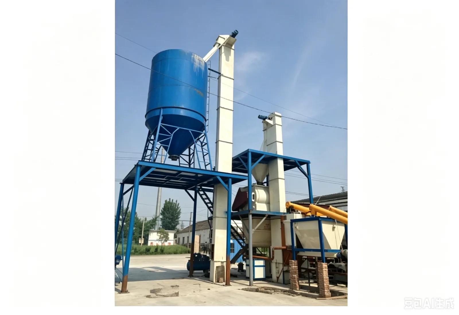
The vertical bucket elevator is a series entry classified by its purpose — vertical transfer — and may use a belt, plate chain or ring chain as the traction element. Selection should not fix the construction first and then look for an application; instead, confirm the material, throughput, lift height, feed continuity and discharge direction, then compare how the various bucket and traction arrangements fit.
Powders and fine granules call for more attention to sealing, dust escape and carryback; granules and small lumps also require assessment of feed impact, bucket strength and the discharge path. Fragile material means controlling belt speed and drop height, while abrasive material means checking the wear allowance on contact parts. Only once these conditions are clear can the head section, casing, boot, drive and tensioning configuration be settled.
A vertical bucket elevator may use belt, plate-chain or ring-chain traction. Belt construction is commonly used where running is relatively smooth and material impact is reasonably controlled; plate-chain construction suits sustained load and higher bucket forces; ring-chain construction requires particular attention to the chain, sprockets, tensioning and lubrication. None of the three is absolutely superior independent of material and layout — the choice rests on duty match, maintenance conditions and project boundaries.
| Design stage | Questions to answer | Effect on the equipment |
|---|---|---|
| Material receiving | Is supply continuous, and does it contain foreign objects or large lumps | Determines the inlet, buffering and boot anti-blockage design |
| Vertical lifting | What are the lift height and target flow rate | Determines traction element, buckets, drive and overall machine height |
| Top discharge | Where is the downstream equipment, and what drop height is allowed | Determines the head section, discharge direction and guide structure |
| Cleaning and servicing | Are changeovers, cleaning or frequent maintenance required | Determines inspection doors, cleanout openings, platforms and access |
| Control and protection | When may it start, and how does it stop on a fault | Determines level, blockage, misalignment, speed and emergency-stop interlocks |
Engineering drawings should show the receiving hopper, upstream conveyor, elevator, discharge chute, surge bin and downstream equipment together — not just the lift height. For powders, mark the dust-extraction interfaces and sealing boundaries; for granules and seeds, mark transfer drop heights and the points where breakage may occur. Space should also be kept around the machine for changing buckets, servicing the drive, cleaning the boot and installing platforms and ladders.
Before start-up, confirm that inspection doors are closed, protective devices are intact, the boot is free of accumulated material and the upstream material state is normal. During operation, watch current, noise, vibration, discharge and detection signals. At planned maintenance, inspect the traction element, bucket fastening, sprockets or pulleys, bearings, gearbox and seals according to actual operating conditions; record the location and trend of any wear found so spare parts and shutdown windows can be scheduled.
If a large surge arrives from upstream, material can accumulate in the boot and cause a blockage; if the discharge end is obstructed, carryback or overflow can appear near the head section; and if the upstream feed is not stopped before maintenance, personnel entering the service area face the risk of material continuing to fall. These risks should be addressed together through process interlocks, mechanical guarding, site procedures and training.
Acceptance testing should use the material agreed by both parties to check loaded operation, conveying rate, overflow, carryback, vibration, noise and service access. The quotation should state whether the supply is a single machine, a unit with platforms, or a complete scope including upstream and downstream interfaces, and should list drive, buckets, sensors, guarding, spare parts and services.
Recommended next step
Connect pretreatment, pressing, filtration and packaging into one practical production route.
Check hot-press, cold-press and small-shop models by batch capacity.
Open pageMatch cleaning, crushing, roasting, pressing, filtering and filling equipment.
Open pageCompare price, capacity, process, operation and startup requirements.
Open pageSend the material, target output and destination for a matched factory quote.
Request quoteReview additional machine, process and buyer resources on hydraulic-oil-press.com.
Open website