Compare machine models
Check hot-press, cold-press and small-shop models by batch capacity.
Open page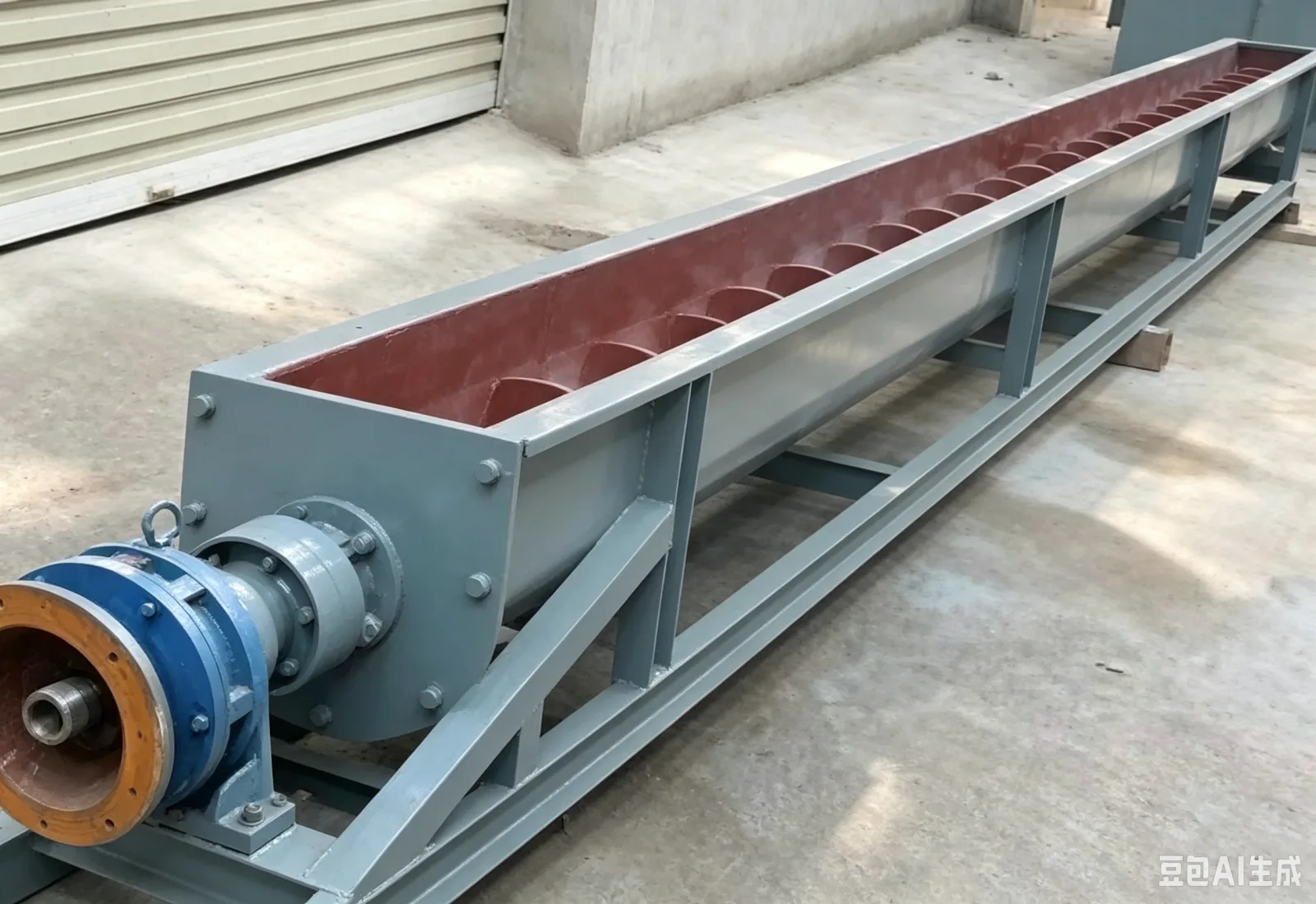
The U-trough screw conveyor handles horizontal transfer of powders, granules and small lumps that can be advanced by a screw, and can also be used at a shallow incline once the duty has been calculated. It commonly connects a receiving hopper, storage bin, elevator, mixer or the next process machine. Actual conveying capacity is set jointly by screw diameter, rotational speed, fill ratio, material flowability and feed continuity.
The basic construction includes the U-shaped trough, screw shaft, drive unit, inlet and outlet, end bearings and top cover. Whether a sealed cover, inspection openings, cleanout openings, liners, hanger bearings and a level interface are needed should be confirmed against dust, material adhesion and service conditions. Before installation, also check the inlet position against the clearances required by supports, flanges and hanger bearings.
The gearbox turns the screw shaft, and the material moves toward the discharge end under the push of the flights and the restraint of the trough wall. Conveying is not a simple case of "faster means more": excessive speed can increase material tumbling, wear and power fluctuation, while overfilling can pile material at the feed section or increase bearing load. Horizontal conveying is generally easier to control; as the incline increases, the tendency to flow back and the effective conveying rate must be recalculated.
This construction is better suited to powders, granules and small lumps with normal flow behavior. Highly adhesive, long-fiber, very fragile, easily bridging material, or material that cakes inside the trough, should be validated by a sample trial first. Where material temperature, dust or hygiene conditions impose special requirements, the trough material, sealing, insulation, cleaning and dust-extraction interfaces should be settled at the same time.
| Component | Function | Confirm before ordering |
|---|---|---|
| Screw flights and shaft | Advance the material and carry the torque | Diameter, flight form, wear requirements and section connection method |
| U-trough and cover | Contain the material flow and control dust escape | Open or closed, inspection openings, access doors and cleanout openings |
| Hanger and end bearings | Support the screw shaft over longer machine lengths | Number and arrangement, lubrication method, isolation from the material |
| Inlet and outlet | Connect upstream and downstream equipment and affect feeding | Opening position, flange form, gates and anti-blockage clearance |
| Drive and control | Provide speed and start/stop control | Motor and gearbox, variable-frequency drive, overload and interlock signals |
The machine body should sit straight on its supports, and the foundation and framework must carry both operating load and maintenance personnel load. Feeding should not be persistently biased to one side, and the conveyor should not be force-started after material has accumulated while stationary. Routine checks should include fasteners, gearbox oil level, bearing condition, abnormal vibration, cover sealing and residue at the discharge end. Before shutdown cleaning, power must be isolated and it must be confirmed that the upstream bin cannot continue to discharge material into the trough.
| Symptom | Check first | Approach |
|---|---|---|
| Rising current or slower discharge | Feed rate, material caking, foreign objects and bearing condition | Stop feeding first, then clean and inspect under the safety procedure |
| Trough leakage or dust escape | Cover plates, flanges, seals and negative-pressure interface | Correct the mating faces and seals, and review the dust-extraction boundary |
| Abnormal noise or vibration | Hanger bearings, screw alignment, fasteners and foreign objects | Shut down and inspect; continued greasing is not a substitute for fault-finding |
| Excessive residue on the return | Clearance between flights and trough, material adhesion and cleaning method | Adjust the construction or process conditions, with a sample trial if needed |
Trial running should check feeding stability, blockage, backflow, bearing temperature rise, noise, sealing and residual material after shutdown. The quotation should state whether the motor and gearbox, trough, screw shaft, hanger bearings, cover plates, supports, controls and safety guarding are included; installation, dust-extraction ducting and site cabling should be listed separately.
Recommended next step
Connect pretreatment, pressing, filtration and packaging into one practical production route.
Check hot-press, cold-press and small-shop models by batch capacity.
Open pageMatch cleaning, crushing, roasting, pressing, filtering and filling equipment.
Open pageCompare price, capacity, process, operation and startup requirements.
Open pageSend the material, target output and destination for a matched factory quote.
Request quoteReview additional machine, process and buyer resources on hydraulic-oil-press.com.
Open website