Compare machine models
Check hot-press, cold-press and small-shop models by batch capacity.
Open page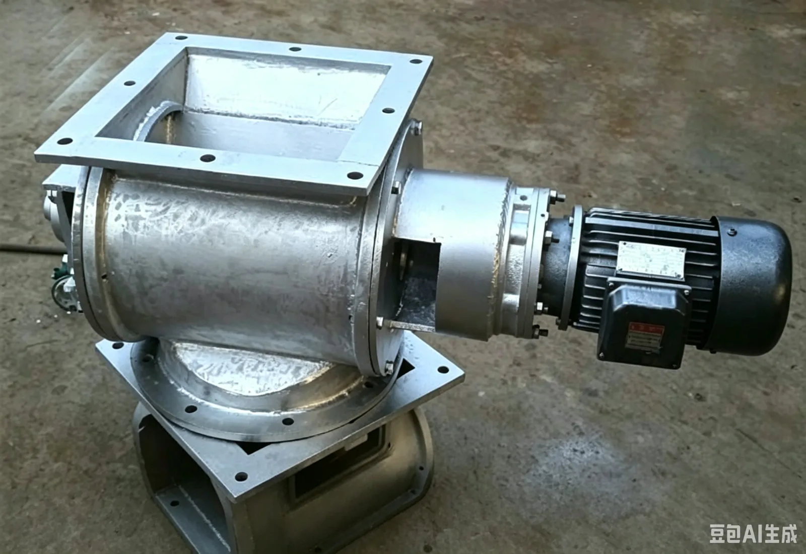
A stainless steel rotary airlock can be mounted below a bin, dust hopper, screening machine or conveying system, discharging bulk material at a controlled rate through the rotor pockets. It may act as a feeding device, and it may also reduce air leakage between adjacent process sections operating at different pressures. Suitability depends on particle size, flowability, temperature, pressure difference and the requirements placed on contact materials.
Confirm the contact materials of the casing, rotor and end covers, the inlet and outlet form, the number of rotor vanes and the pocket size, together with shaft-end sealing and the drive arrangement. Material containing long fibers, easily caking particles or larger lumps can cause jamming or abnormal wear, so a sample assessment should be carried out first. Where washing or frequent cleaning is required, dismantling access and the emptying method should also be written into the technical scope.
Material enters the rotor pockets from above, the rotor indexes pocket by pocket under geared drive, and the material discharges below. The actual fill of each pocket is not constant — it is affected by material flowability, upstream level, rotational speed and pressure difference. The unit can therefore provide a controlled discharge rate, but it does not replace a high-accuracy metering device. Where the unit also serves as an airlock, the clearance between vanes and casing, the shaft-end seals and the upstream/downstream pressure difference all form part of the technical review.
Stainless steel is normally chosen to meet a specific contact-material, cleanliness or corrosion-resistance requirement, but the material of the casing, rotor, shaft, fasteners and seals should still be stated individually. For food-related projects or projects with product changeovers, the material grade is not the only issue: dead spots in the pockets, the extent of dismantling possible, the emptying route, the cleaning medium and the post-cleaning reassembly check all matter. Moist material can build up at the root of the vanes, so allow for inspection and cleaning access.
| Item | Effect | What must be confirmed |
|---|---|---|
| Rotor pockets | Set the theoretical discharge volume per revolution | Vane count, pocket size and allowable particle size |
| Shaft-end seals | Affect material leakage, air bypass and maintenance frequency | Seal type, pressure difference, temperature and lubrication limits |
| Inlet and outlet | Determine connection to the bin and downstream equipment | Round or square opening, flanges, mounting orientation and drop space |
| Drive assembly | Determine speed, torque and interlocking | Motor, gearbox, variable-frequency drive and guarding requirements |
| Cleaning arrangement | Affects changeover and service time | End-cover removal, inspection openings, emptying and tool clearance |
Persistent bridging above the unit should be avoided, and the outlet shape of the bin or hopper should promote even flow into the rotor. After installation, check that the rotor turns freely, that flanges are aligned and that drive guarding is complete. Do not treat abnormal friction noise, temperature rise or intermittent discharge as normal during operation. For maintenance, disconnect power and lock out upstream supply, and confirm that the rotor has stopped and no residual pressure difference remains before removing end covers or guards.
Acceptance testing should check no-load and loaded rotation, discharge continuity, seal condition, temperature rise, noise and residue. The quotation must itemize the body, rotor, gearbox, motor, coupling, seals, flanges and spare parts; the material, quantity and replacement conditions for wear parts should be confirmed on the order.
Recommended next step
Connect pretreatment, pressing, filtration and packaging into one practical production route.
Check hot-press, cold-press and small-shop models by batch capacity.
Open pageMatch cleaning, crushing, roasting, pressing, filtering and filling equipment.
Open pageCompare price, capacity, process, operation and startup requirements.
Open pageSend the material, target output and destination for a matched factory quote.
Request quoteReview additional machine, process and buyer resources on hydraulic-oil-press.com.
Open website